 |
 |

Valve Stem Seal
Replacement
Guide and photographs by Jason Zuress
Edited and Produced by Joshua Langevin
Note: This procedure is explained with the heads still attached to the block.
Tools/Parts Needed: (Rotunda Tool Kit)
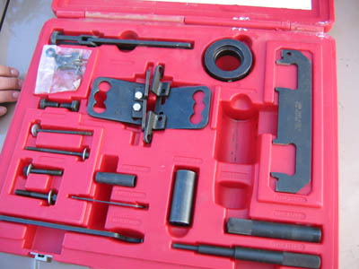
-Valve Spring Compressor w/ brackets: T89P-6701-C
-Air Compressor, hose, and adapter
-Valve Stem Removal Tool: T89P-6510-D
-Valve Stem Replacement Tool: T89P-6510-C
-Valve Stem Seals w/ Plastic Straw (includedd with seals)
- Magnet
-Long Ratchet
-Needle Nose Pliers
-Pick
-Cam Seal Replacer
-Cam Seal Expander
-Cam Seals
-Silicone Gasket and Sealant
- Cam Position Tool: T89P-6256-C
If your SHO burns oil at start up (puff of smoke at start up), you can remedy it by replacing the valve stem seals. Whether you do it with the heads on or off, be prepared to take on a VERY time consuming and tedious job. I replaced my seals because I was already installing new cams into the car. I did not have any smoke on start up, but I took care of the seals while I had the car apart. Once everything was apart, it took me 7 hours just to replace the seals. I did not have any head gaskets on hand, so I chose to do the procedure with the heads still attached to the block. This job is not for everyone, but if you decide to accept the job, I have written this article as a guide only. DO NOT substitute this for an actual manual (preferably a Helms).
To get to the valve stem seals you must follow the upper 60k instructions for tear down. Follow the directions all the way to step 11. You must also remove the upper timing belt cover and timing belt for access to camshaft sprockets, directions can be found in the front 60k procedures. Once you have torn down the motor to this point, you must now remove the camshafts.
1. First remove the sprockets (belt side) by removing the 3 bolts attached to each sprocket. After the bolts are removed, gently wiggle the sprockets off of the cam. There will be a small dowel that may fall out once the sprocket has been removed. Be careful not to lose the dowel as it is needed for alignment upon installation.
2. Next, remove the upper-inner timing belt cover. Be careful not to drop the bolts into the lower timing belt covers. If you do, you will have to remove them to retrieve the bolts.
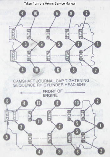
3. For the camshaft removal, you must uniformly loosen the cylinder head camshaft journal. If the caps are not uniformly loosened, camshaft damage may result. Once caps are removed, note position and direction of they way each cap was installed. You must install each cap in the same position and direction as they were initially installed
Opposite sequence of picture shown
4. After the caps are removed, remove the camshaft timing chain sprocket tensioner mounting bolts.
5. Next, remove camshafts together (intake & exhaust) with timing chain and timing chain sprocket tensioner. Set everything aside.
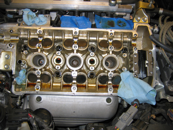
Now we will move onto the removal and replacement of the valve stem seals. (Note: you can set up the valve spring compressor kit at anytime before the tool is needed. In my "how-to", I will set it up just before the tool is needed. You may also want to set up a trash bag around the outer portion of each head. Also be sure that you have plugged the oil return passages. Each valve contains two very small keepers that can easily be dropped and lost. ONLY replace one valve at a time
1. Remove your spark plugs. You can remove one at a time, or you can remove them all at once. Just be sure that you do not drop anything in the cylinder.
2. Next, hook up your air compressor, hose and adapter in the plug well to pressurize the cylinder.
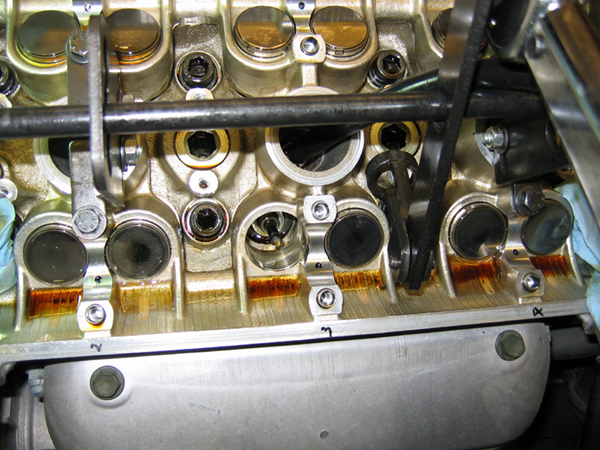
3. Remove bucket and shim together with a magnet. It should pull straight out. Set both aside
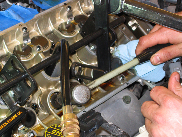
4. Before compressing the spring, you must tap the spring retainer with a hammer to break the fit between the retainers and the valve stem. If you do not do this, you risk dropping a valve into the cylinder. Removal of the head would be required to retrieve the valve
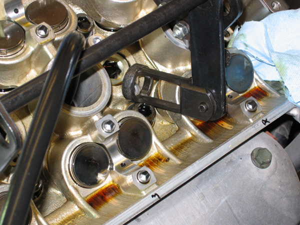
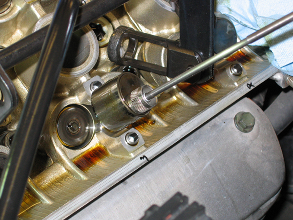
5. Now you can bolt the spring compressor kit to the head. The kit is adjustable and bolts up to the cylinder head caps. The kit does not come with a rod to use, so you will have to acquire one elsewhere. I just happen to have something that worked.
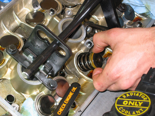
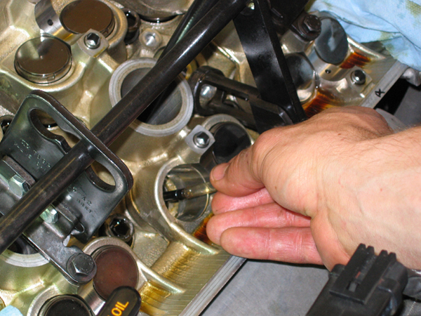
6. Now you must attach a long ratchet (the longer it is, the more leverage you will have) to the spring compressor. Next, compress the spring and use the magnet to remove the keepers. If the keepers do not come out with a magnet, use a pick or other tool to move them around a bit. Then you should be able to pick them up with the magnet. Set the keepers in a safe place as they can become lost VERY easily.

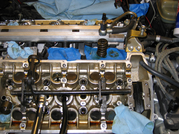
7. Next, remove the spring and retainer and set aside. Be sure and note the position of the painted end.
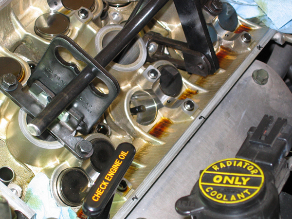
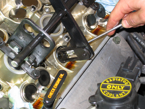
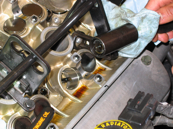
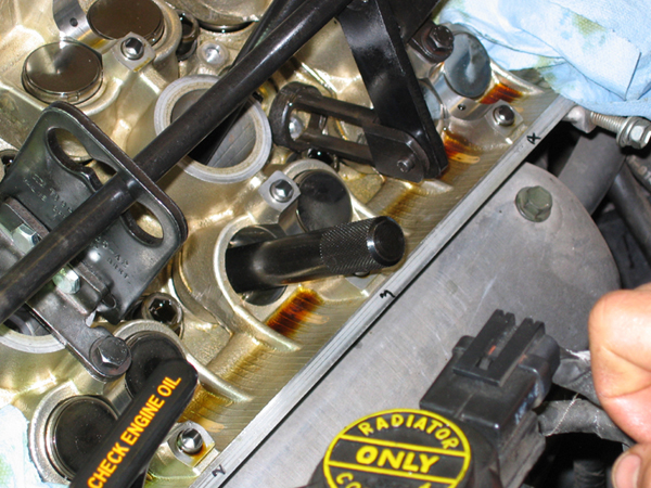
8. Next, insert the clamp portion of the valve stem seal removal tool over the valve stem. Push until you are at the bottom of the head.
Then insert the sleeve over the clamp and push until fully seated
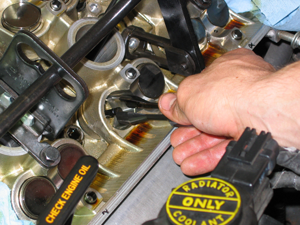
Now pull the tool out and the seal should come with it.
9. Now you can install your new seals. Be sure you use the correct seals for the intake and exhaust. If you mix them up, the exhaust valve WILL leak. The seals I used were included in the Fel-Pro Kit; the intake seals were brown and the exhaust were black.
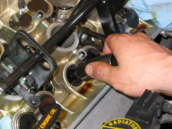
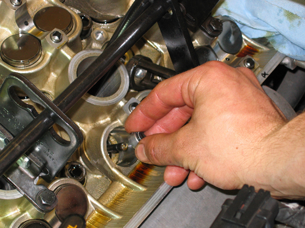
Now you must lube the straw included with the valve stem seals and slide it over the valve stem. The straw is used to prevent damage of the seals from the notches in the valve.
Next, oil up the seal and push it down by hand as far as you can. Now remove the plastic straw and store for use on the other valves. Finally, use the installation tool to push the seal on until it bottoms out.

Now we have to put it back together ;-)
10. Replace valve spring and retainer. Note where position of paint is.
11. Compress spring and use a needle nose pliers and a pick to position the keepers. This is the MOST time consuming part of the whole project. I have taken up to 10 minutes just for installing. Once in place, slowly release the pressure on the spring to make sure the keepers take a proper seat. If not, you must compress the spring and reposition the keepers. When I started to get the hang of it, I put in one keeper on the side with the largest gap, then I pried the spring over to give the opposite side the gap. Then I was able to get the other keeper in. I am told there is a tool that makes this process go much easier. Luckily, I was told after I had already completed the job.
12. After the keepers are set, you can now install the buckets by sliding them on top of the valve. Make sure you are straight or you will wedge the retainer in and have a hard time getting it out.
Now you have replaced one valve stem seal, you only have 23 more to go. After all seals have been replace, reverse removal directions to install.
Installation of Cams (Because I do not have pictures of this process, the following instructions were taken from the Helms 1995 Taurus/Sable Manual, pp. 03-01B-25 thru 03-01B-27)
1. If you have moved your timing chain out of timing, align white painted link with timing mark on camshaft sprocket. Marks on sprockets will be on the outer sides of the chain.
2. Rotate camshafts approximately 60 degrees counter clockwise on the RH(rear) head. Set timing chain tensioner between camshaft sprockets and position camshafts on cylinder head.
3. Apply a coat of engine assembly lubricant to camshaft journals and install cylinder head camshaft journal caps 2 through 5 (ARROWS POINT TO FRONT OF ENGINE, LOWER NUMBERS 1 OR 2 START AT FRONT OF ENGINE). Loosely install cylinder head camshaft journal cap retaining bolts. Be sure caps are installed in their ORIGINAL position!!!
4. Apply silicone gasket and sealant to outer diameter of new camshaft front seal and seal seating area on cylinder head.
5. Install camshaft front seal with cam seal replacer.
6. Apply a 2.5mm bead of silicone gasket and sealant to number 1 cylinder head camshaft journal cap and install cylinder head camshaft journal cap while holding camshaft front seal in place with cam seal replacer. Loosely install bolts
7. Caution: The number 5 cylinder head camshaft journal caps function as thrust bearing for the camshaft. Always tighten number 5 cylinder head camshaft journal caps first!
Note: For LH (front head) camshaft installation, apply pressure to timing chain tensioner to avoid damage to cylinder head camshaft journal caps.
Tighten cylinder head camshaft journal caps in sequence shown using two step method. Tighten to 71-106 lb-in, then tighten to 12-16 lb-ft.
8. Caution: LH and RH timing chain tensioners are different. Be sure to install timing chain tensioners on the proper side.
Position timing chain guide and timing chain tensioner and install retaining bolts. Tighten bolt to 11-14 lb-ft
9. On RH head, rotate camshafts 60 degrees clockwise and check for proper alignment of the timing marks. Marks on timing camshaft sprockets should align with valve cover mating surface.
10. Set cam position tool on camshafts to ensure correct positioning. Flats on tool should align with flats on camshaft. If tool does not fit and/or timing marks will not line up, repeat procedures from step 1.
11. Now you can install timing belt, valve covers, and intake manifold as stated in the upper and lower 60k procedures. Before installing the valve covers and intake, you can check the gapping on your shims to ensure they are within spec.