 |
 |

Rod
Bearings Replacement
Pictures and Guide by Jeremy Last
Edited and produced by Joshua Langevin
Important things you’ll need:
Jack and Jack stands (or some way to hold the front up, I put both up)
Any form of PB blaster/Free All
Oil to re-fill the engine
A pan to catch the old oil in that you drain out
Ratchet socket wrench
Extensions
Torque wrenches, ft and in. (might have to use an inch pound and convert for low ft-lb values)
Crescent wrench/ Channel locks.
10,12,13,15mm sockets and a socket U-joint that’ll work with 12mm socket. (19mm optional)
Rod bearings
Assembly lube
Black RTV
New exhaust flange donut gasket
Acetone
Rags
Soft wire brush/es
Small scraping/putting knife
Pocket knife
A light to hang under the car and possibly a flashlight
Optional replacement oxygen sensors (might as well do it now). Optional coolant replacement and regular screw driver
Gasket material (I used non-asbestos high temperature oil “OK”)
Eye protection, way to much crap like oil and dirt falls on you
Plenty of time and patience, you won’t be doing this unless your hate yourself but love your SHO :)
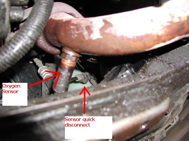
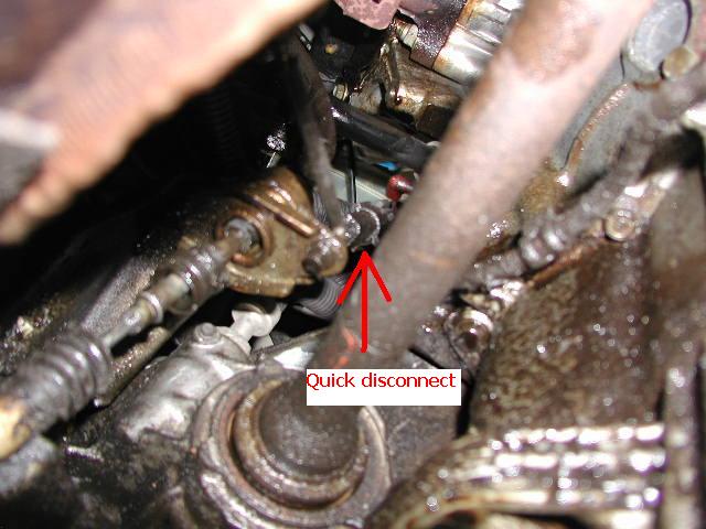
1. Before you start any thing, get it up on jack stands and disconnect the battery for safety. I choose to remove my Y-pipe first, as it takes up a lot of room. First thing I did was remove the old oxygen sensors that I replaced (you don’t have to, but while your in Rome). Start by disconnecting them. You can see the oxygen sensor, just follow its wire until you find the quick disconnect. Here are some pictures to help guide you.
(Front)
(Rear) – Please note I have a cable shifter in this picture, yours may be different.
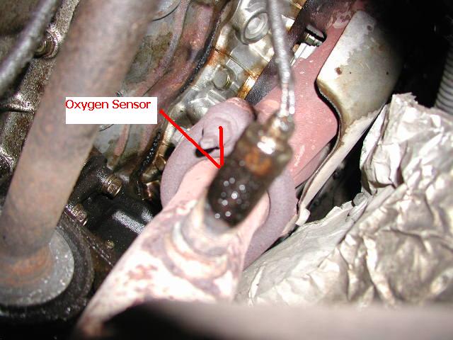
2. Then with Crescent wrench/ Channel locks remove the oxygen sensors.
(Front)
(Rear)
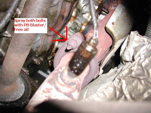
3. Next to work on the Y-pipe itself, spray PB Blaster/ Free All onto these spots. (Front and back exhaust studs and bolts)
4. While those are soaking, you’ll need an 18mm socket to take these two bolts off the exhaust to let the Y-pipe free. (note one of mine is loose in the picture, it shouldn’t look like this before you start)
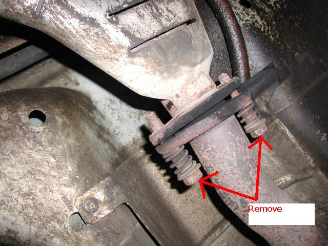
5. Now take the front and rear exhaust stud nuts off. My suggestion is a putting pipe on the end of the ratchet socket wrench for leverage if you don’t have a long breaker socket wrench (really long socket that may not have ratchet function).
Be careful as the Y-pipe with cats is not light in the sense that you’d let it fall on your face. You might have to pull down on it some because the hanger attached to the oil pan will hold it.
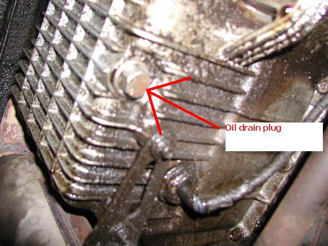
Now is a good time to drain the oil. Beware this little engine carries 5 quarters, and it will stream out from directly under the plug hole, be ready when you take this bolt out.
6. Now when it is drained you can remove this oil level sensor and push it out of the way some where, to get more slack for moving it out of the way simply take out one of the pan bolts that holds the wire. (This picture is when I was done, the oil pan is cleaned, and it makes it easier to see what I’m typing about)
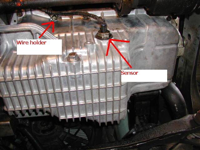
7. After removing this, take the rubber and plastic piece off the pan (if it sticks) and put it on the sensor so you don’t forget about it, if it stays on the sensor then awesome. Mine however didn’t, and if you read on it, it’ll say what side toward the engine.
Next is the starter.
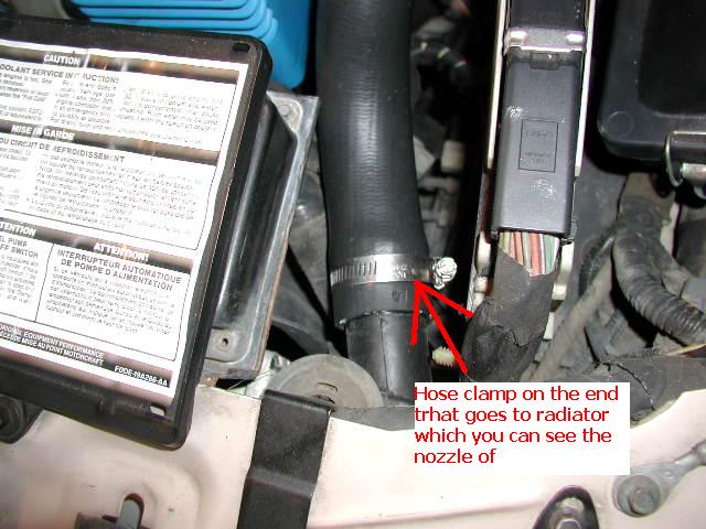
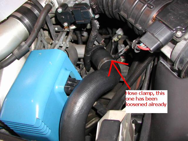
This is optional, but I had my fluid drained from my radiator. I removed the top radiator hose for easier access to see what I was doing. If yours isn’t drained, you can drain it, then remove these hose clamps and pull the hose off. (I mostly did it so you could see)
(Front Hose Clamp)
(Rear hose clamp) – already loosened and pulled back, it’s down in there a little bit.
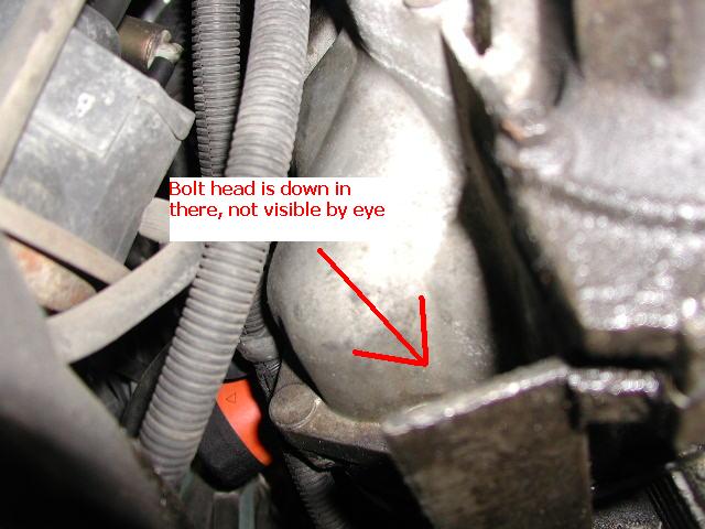
8. Now the fun beings, locate the starter on the front of the engine, and remove the rear wire which should be a 10mm bolt. It’s clearly visible; however these next few are not. Here is where the bottom 13mm bolt is to the starter.
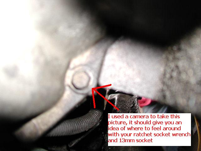
9. Now the top one, first there is a 15mm nut holding on the wire. Then there is a stud with a 13mm nut welded onto it. Start by taking off the 15mm nut, moving the wires out of the way, and then the 13mm. The starter should be free and not require any thing to get it loose, however a rubber hammer on the base would work. You shouldn’t need a rubber hammer, but if you do, hit it at the base only, the rear tube is not on real good (mine was loose before I took my starter out). Here is a shot of where the ratchet socket wrench will go, from the bottom.
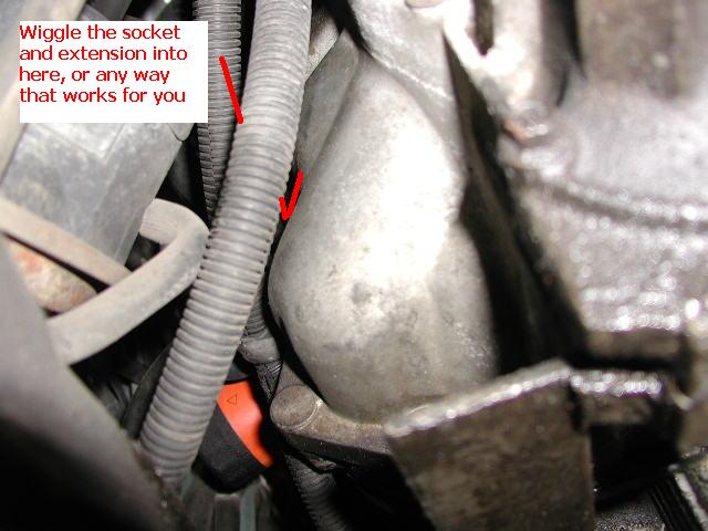
Now here is a view from above with the top radiator hose removed.
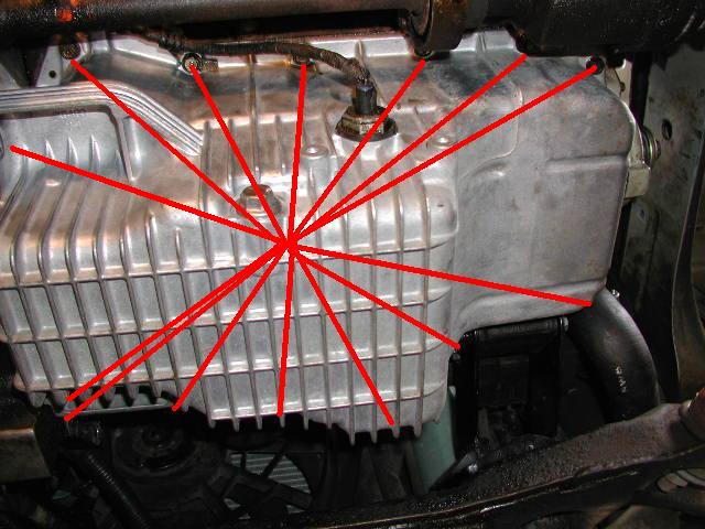
10. Again, after removing the 15mm nut and the 13mm stud, the starter should be free and wiggle out. Whew! Now we are to all the easy stuff. Now you are going to remove all of the bolts and the nuts holding onto the pan, they are all 12mm. (Back of oil pan) – not the front of the pan bolt and nut indicators may or may not be more then there is, I don’t have a good shot of this due to angles and being so close to the ground.
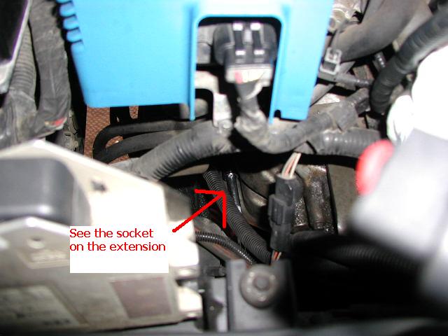
11. Now be aware there are some almost hidden bolts and nuts. You’ll need a U-joint socket to get the one deep in the back.
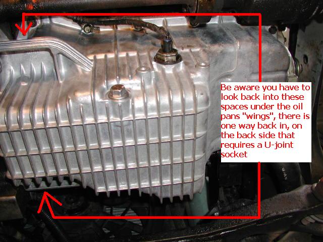
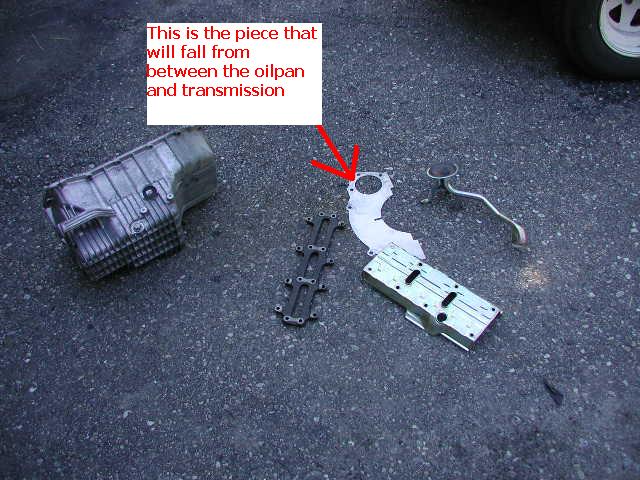
12. Your pan should come free after these are removed and a gentle nudge with a little force, or a bump from a rubber hammer. If you think it’s not moving, and is like rock, double check you got all the bolts and nuts under the “wings” or in them. Be careful a small metal sheet that’s a cover for the flex plate will fall from between the oil pan and transmission.
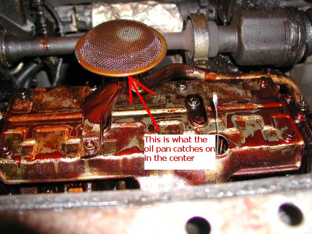
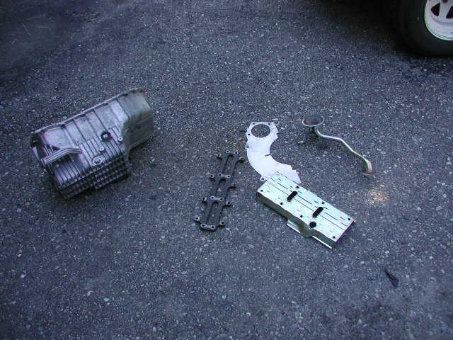
13. Getting this thing out is tricky. It can be done, don’t be discouraged. There is a oil pump pickup that has to come out of the splash shield. Here is the oil pickup tube so you understand what the oil pan will hang from if it’s not free.
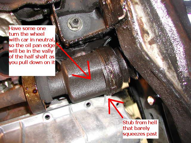
14. The front of the pan will be hard to get past the half-shaft. I had some one turn the wheel for me to aid with this, I had to pull on it to squeeze it down past. The little stub is kind of worthless, it better be for structural strength or I’ll grind it off next time.
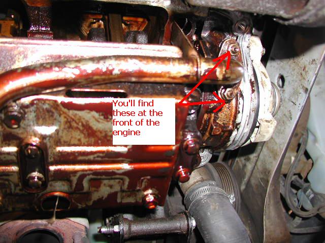
15. Yeah I bet you’re really happy you decided to do this now! Now you can remove the oil pickup tube’s 10mm nuts at the front of the engine.
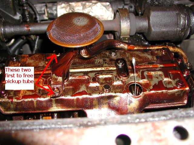
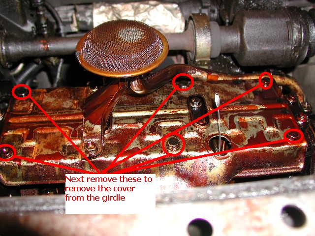
16. Next remove the 12mm bolts from the oil pickup tube on the girdle, and then the cover.
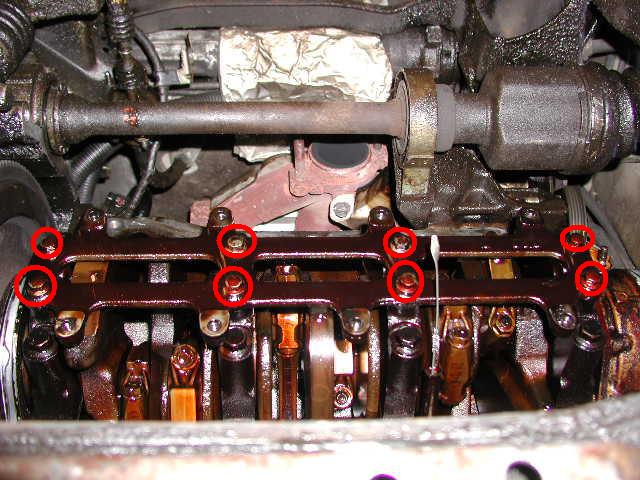
17. Next to gain access to the rod’s you have to remove the girdle from the main caps, they are 12mm as well.
18. Now to what you wanted to do to begin with!
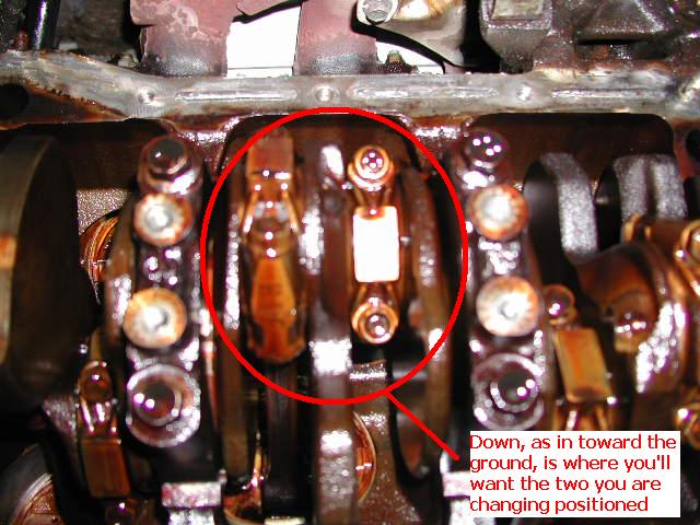
You’ll have either turn the wheel with the car in gear to turn the engine, or use a 19mm socket on the crankshaft bottom pulley bolt. Refer to step Front 60k guide on how to get to this, it’s in step 3 at the beginning. DO NOT loosen this at this time, I just refer to the other guide so you know how to turn your engine over with the car in neutral, with out the starter. You turn the engine until the rods you want to work on are down, and about to, or starting their way back up.
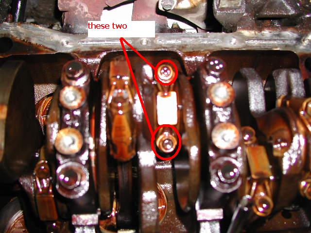
19. Now you can remove from one rod the 13mm bolts.
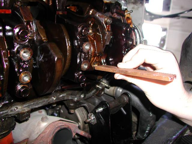
20. To remove the rod cap, use some thing soft like wood or copper on the stud end, and a hammer to knock the rod loose. If you use wood be aware, you don’t want any thing going into the engine, I used a piece of copper to hit the hammer against. It should only take a few light taps. Another suggestion I don’t like as much, from another guide (written) “Loosen the two rod end cap nuts and unscrew a few turns. With the 13mm socket and extension still on the nut, tap on the socket extension with a hammer to separate rod end.” The reason I don’t like this is because it’s harder on the threads, and some peoples sockets are to deep to do this very well, or can hit the rod cap when the rod brakes loose from the cap.
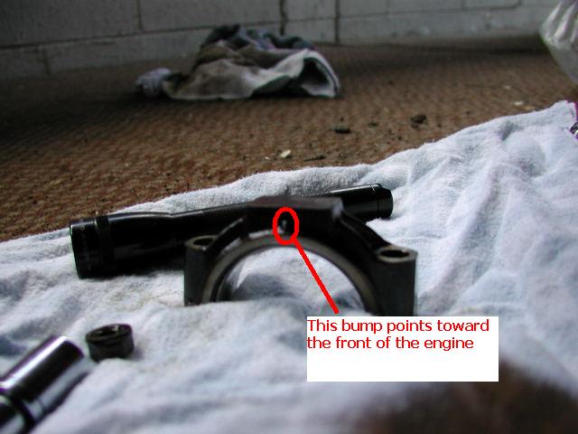
21. Once it’s loose, you can pull the rod cap off pretty easy. You’ll notice a bump on the ridge right below the flat surface, this signifies to point toward the front of the engine on all the rods.
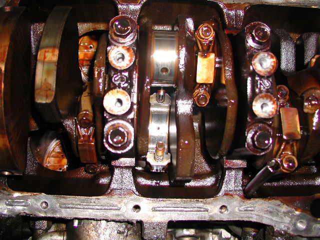
22. Once the rod cap is off, you can pull the bearings off the crankshaft or off the rod/rod cap be careful and try not to scratch the crankshaft or rod and rod cap surfaces. Here is what the rod and crankshaft will look like, with no bearings on them. Also if the rod will not push up, it is because no valves are open and it’s on the compression stroke, simply turn the motor over more until it’s easy to push up, just be careful not to bang the studs on the crank.
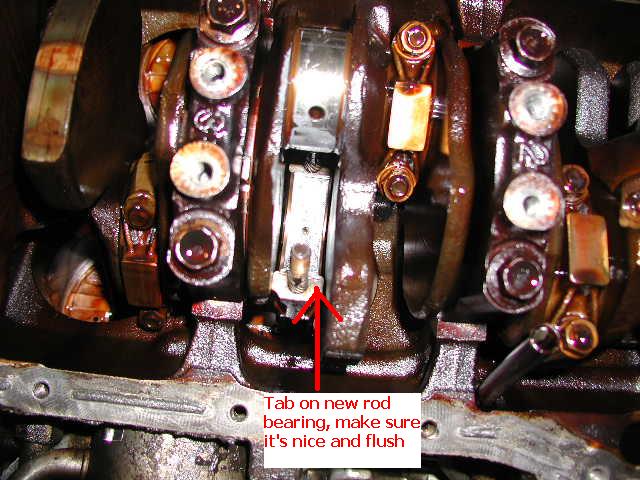
23. Now grab the new rod bearings, you’ll find they have a bent out tab on one end; this corresponds with notches on the rod and rod cap. All of the bearings are the same, don’t worry about which one goes to which. Remember before you put them in, apply the assembly lube. On the outside don’t apply to much, as it is only to get a little oil passage going, nothing actually moves, on the inside make sure it’s covering the bearing, a little access won’t hurt, it’ll just squeeze out. Don’t cake it, remember this is tolerance area meant for only so much oil, just make sure it’s got a little more then a film of assembly lube over it. You will then have to position it into the rod, make sure the tab is in the notch, and try to get the bearings ends flush with the rod as best as possible. Do the same for the rod cap bearing but on the rod cap. If they aren’t very flush it can cause problems, not flush by less then 1mm at worst lets say, can probably even it’ self out when tightening the rod cap. Just do your best as that’s all you can do, you’ll know if it’s seriously out of alignment.
24. Now you can put the cap with its new bearing back on. Torque them first to 22-26lb-ft, and then torque to 33-37lb-ft. I would not keep clicking the torque wrench more then two, max three times if you have a bunch of extensions with slack, over tightening will ruin the bearings and crank fast.
Repeat the process for all rods bearing replacement.
Now after you’ve finished all of the rods, it’s a good time to start getting ready to put things back together. I personally had my parts cleaned at a machine shop and went over them by hand myself after.
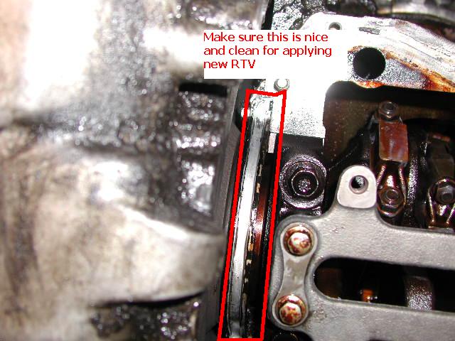
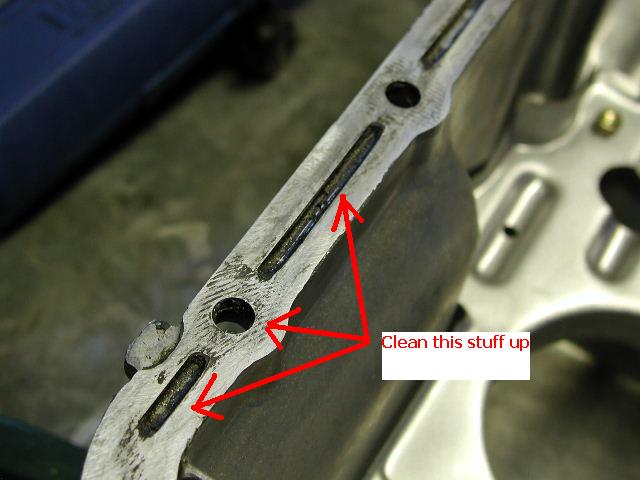
25. You’ll want to scrape and clean up the blocks mating surface for the oil pan, and around the gaskets. I put the girdle on, but didn’t torque it, just to keep me from getting my arms or hands down into the rod and crank area.

26. The back gasket area is a little bit harder to get too, but clean it up well.
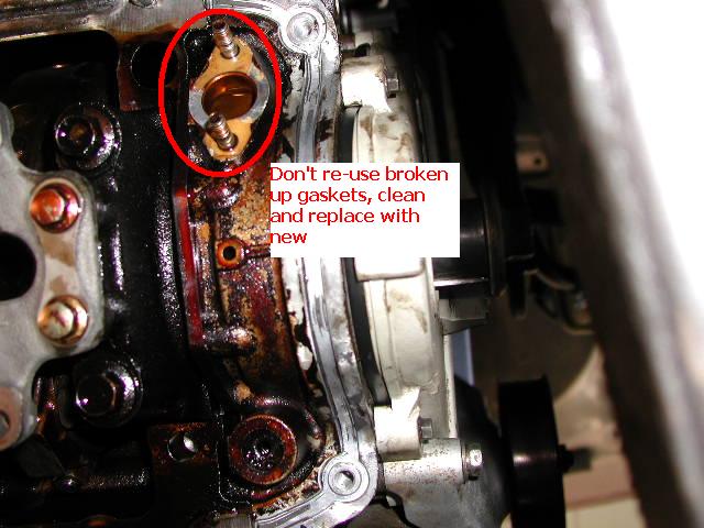
27. I choose to make a new gasket for my oil pickup tube. If yours is in super good shape you could reuse it, I scraped mine off with a pocket knife as well as possible. As you can see it wasn’t in very good shape. If you do reuse it, make sure to clean oil off it as best as possible and use a VERY LITTLE bit of RTV smeared toward the outside of the gasket edges, very thin layer.
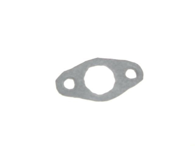
28. Here is my new gasket I made from some gasket material at shucks auto supply.
29. Ok you got it all cleaned up, not put the girdle back on, or if on, torque to 15-24lb-ft (I choose the higher scale as this is for support, and doesn’t directly effect any bearings or any thing, I could feel it snug very well as it got nice and snug right around 24lb-ft). Please note the 12mm bolts for this have a ROUND top.
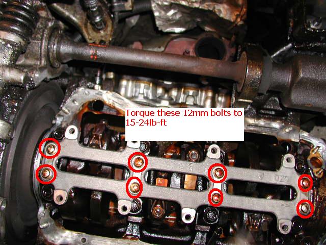
30. Now you can put the cover back on with it’s 12mm bolts with the DISHED top back on, don’t forget two are used for the oil pickup tube, don’t put them in yet. The 12mm bolts should be tightened to 62-97lb-in, I however tightened them a little more as it didn’t hurt any thing to get them nice and snug.

31. Ok now to put the oil pickup tube back on. Wipe down around the mating surface on the block and oil pickup tube with acetone, wipe dry, put gasket on studs, put oil pickup tube in place, put 10mm nuts on pickup tube studs, and the 12mm oil pickup holder into the girdle (through the cover). Torque the 12mm bolts to 62-97lb-in according to manual, I tightened them till they where nice and tight, not stressed. The 10mm nuts however, while called for by manual would be 15-24lb-ft, I’ve read they are known to strip easy, I personally think the 62-97lb-in given for the cover, is a reasonable start, and then snug them up a little, you’ll feel it if you go slow, get right to snug and not past. I honestly wouldn’t be surprised if these values are backwards in the service manual, I basically reversed them seeing how every one else’s response to changing rod bearings have been with these items.
Next step the pan! However you should clean it first, clean out all the old RTV, screw driver, putty knife or some thing of sorts, and a soft wire brush work well.
32. Wait before you go trying to put this back on, first clean the mating surface on the bock with acetone, and the oil pan. Next lay some RTV into these spots for the new gaskets, DO NOT put RTV all over the gasket, it is only meant to be on the upside toward engine, side. I used some thing small to spread it around a little. (excuse the pictures of dirty gasket areas, I didn’t want RTV on my camera during re-assembly)
33. After applying RTV wait for 10-15 seconds, and then put the gaskets in. They should stick easy. Make sure you don’t try to put them in upside down, they obviously won’t stay then, but they bend easy so it’s easy to get them upside down.
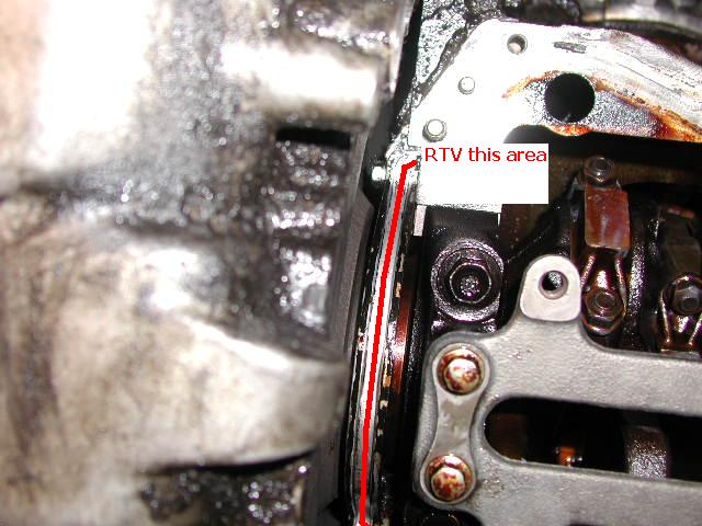
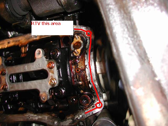
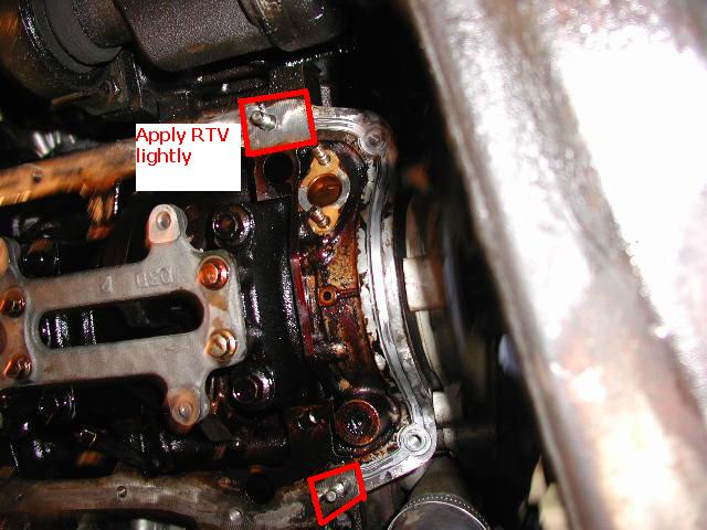
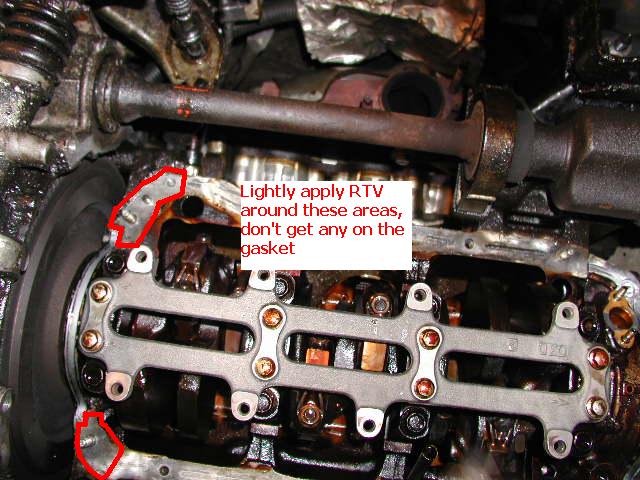
Then apply RTV around these areas lightly, real light.
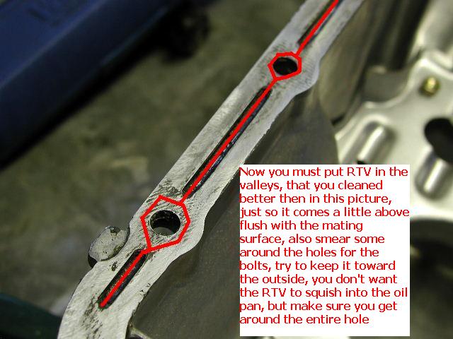
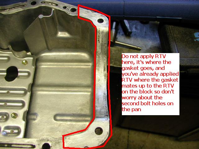
34. Next you have to apply RTV to the oil pan. Fill the cleaned out valleys and smear some RTV around the holes for the bolts.
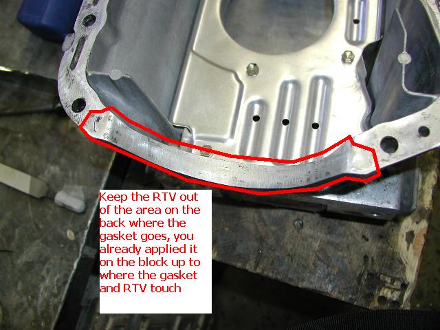
35. DO NOT put any RTV on these areas where the gaskets are, I instructed applying RTV around the areas in picture #37 and #38, this is so you don’t go to far on the oil pan when RTVing it, you’ve already got RTV where you need it.
The back.
The front.
36. Great job! Ok I’m just trying to build your confidence for putting the pan back on, as you know it magically came off, so now you have to magically put it back on, I can’t really tell you how to do this other then try to do what you did before, but backwards. Put the bolts and nuts back on, don’t forget the one deep in the back (don’t put the bolts on that go through the oil pan wings yet I’ll discuss them in a second). Torque them too 11-17lb-ft, you’ll feel them snug up some where in that range. Don’t forget about the wire holder, and the sensor, however before putting the oil level sensor back on, apply a little RTV on both sides of the rubber grommet, not much, just a tiny bit incase any gap in the threads let oil through.
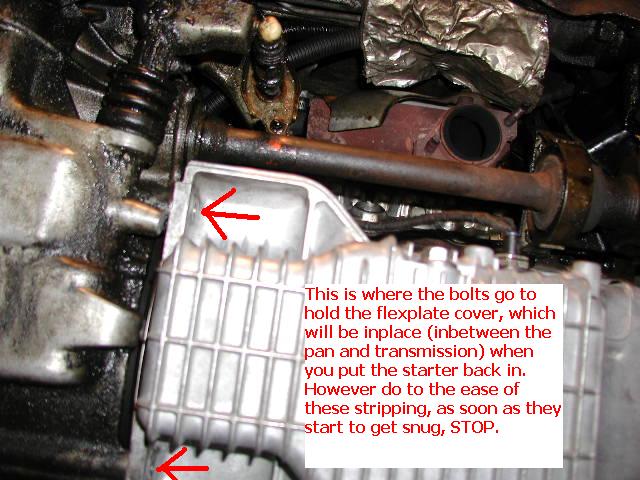
37. You can now put your starter back in, however first sand all the contact points clean on the wires and starter. Use just the opposite procedure to put it back in; do not forget the flex plate cover! Fit the flex plate cover up in there, put the starter on, and put the 13mm bolt and stud in, tighten them well. Then reattach the wire with the 15mm nut, and the rear wire with the 10mm bolt. Now for the bolts that go through the wings of the oil pans to the transmission. As SOON AS they start to feel like they are getting snug STOP. These stripped out so ridiculously easy on mine, that applying a torque of 11-17lb-ft would NEVER work. I didn’t even get them snug. When I pulled them bolts out the threads from the transmission where on the threads of the bolts, and I could unscrew them off the bolt. I’m going to try a deeper bolt now because the hole is deeper then the bolts. In all loss they are just to hold the flex plate cover when the starter’s bolt and stud are not holding it.
38. Put the exhaust hanger back on the oil pan if you took it off (I did to clean it). Put the new exhaust flange donut gasket on, put anti-seize on the Y-pipe to header studs and exhaust flange bolts, put the Y-pipe back in. Get the bolts and nuts pretty tight so you don’t have exhaust leaks, just don’t strip any thing or break the header studs. Apply anti-seize to the oxygen sensors and put them on the Y-pipe, reconnect the oxygen sensors quick disconnects.
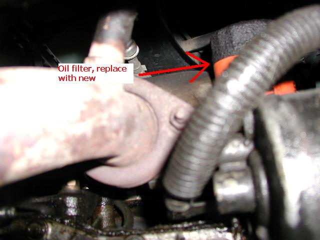
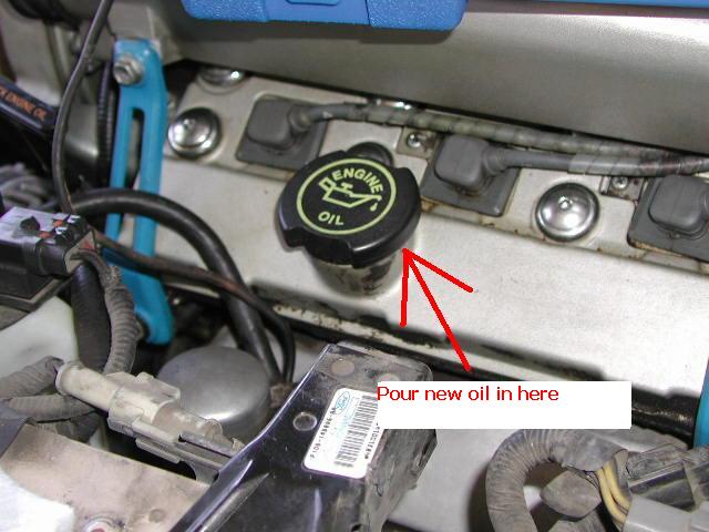
39. Make sure your oil drain plug is not loose. Change your oil filter. Poor in 5 quarters of your choice oil in the oil filling spot on the front valve cover (don’t go to fast, it has to drain down to the oil pan)
40. Replace radiator hose and engine coolant if you removed them; make sure the coolant drain plug is closed on the bottom of the radiator before pouring any coolant into the radiator.
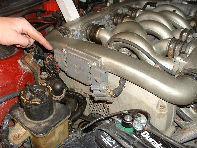
Now disconnect your DIS.
(Yep picture is from 60k maintenance guide)
41. Reconnect the battery.
Now you can crank your engine until the oil light disappears. Do not crank for more then 15 seconds at a time, keep it down to 10 second intervals at most, and pause in-between, it may not take much cranking any how.
Now reconnect the DIS, and enjoy your new bearings.
Edited and produced by Joshua Langevin
Important things you’ll need:
Jack and Jack stands (or some way to hold the front up, I put both up)
Any form of PB blaster/Free All
Oil to re-fill the engine
A pan to catch the old oil in that you drain out
Ratchet socket wrench
Extensions
Torque wrenches, ft and in. (might have to use an inch pound and convert for low ft-lb values)
Crescent wrench/ Channel locks.
10,12,13,15mm sockets and a socket U-joint that’ll work with 12mm socket. (19mm optional)
Rod bearings
Assembly lube
Black RTV
New exhaust flange donut gasket
Acetone
Rags
Soft wire brush/es
Small scraping/putting knife
Pocket knife
A light to hang under the car and possibly a flashlight
Optional replacement oxygen sensors (might as well do it now). Optional coolant replacement and regular screw driver
Gasket material (I used non-asbestos high temperature oil “OK”)
Eye protection, way to much crap like oil and dirt falls on you
Plenty of time and patience, you won’t be doing this unless your hate yourself but love your SHO :)
1. Before you start any thing, get it up on jack stands and disconnect the battery for safety. I choose to remove my Y-pipe first, as it takes up a lot of room. First thing I did was remove the old oxygen sensors that I replaced (you don’t have to, but while your in Rome). Start by disconnecting them. You can see the oxygen sensor, just follow its wire until you find the quick disconnect. Here are some pictures to help guide you.
(Front)
(Rear) – Please note I have a cable shifter in this picture, yours may be different.
2. Then with Crescent wrench/ Channel locks remove the oxygen sensors.
(Front)
(Rear)
3. Next to work on the Y-pipe itself, spray PB Blaster/ Free All onto these spots. (Front and back exhaust studs and bolts)
4. While those are soaking, you’ll need an 18mm socket to take these two bolts off the exhaust to let the Y-pipe free. (note one of mine is loose in the picture, it shouldn’t look like this before you start)
5. Now take the front and rear exhaust stud nuts off. My suggestion is a putting pipe on the end of the ratchet socket wrench for leverage if you don’t have a long breaker socket wrench (really long socket that may not have ratchet function).
Be careful as the Y-pipe with cats is not light in the sense that you’d let it fall on your face. You might have to pull down on it some because the hanger attached to the oil pan will hold it.
Now is a good time to drain the oil. Beware this little engine carries 5 quarters, and it will stream out from directly under the plug hole, be ready when you take this bolt out.
6. Now when it is drained you can remove this oil level sensor and push it out of the way some where, to get more slack for moving it out of the way simply take out one of the pan bolts that holds the wire. (This picture is when I was done, the oil pan is cleaned, and it makes it easier to see what I’m typing about)
7. After removing this, take the rubber and plastic piece off the pan (if it sticks) and put it on the sensor so you don’t forget about it, if it stays on the sensor then awesome. Mine however didn’t, and if you read on it, it’ll say what side toward the engine.
Next is the starter.
This is optional, but I had my fluid drained from my radiator. I removed the top radiator hose for easier access to see what I was doing. If yours isn’t drained, you can drain it, then remove these hose clamps and pull the hose off. (I mostly did it so you could see)
(Front Hose Clamp)
(Rear hose clamp) – already loosened and pulled back, it’s down in there a little bit.
8. Now the fun beings, locate the starter on the front of the engine, and remove the rear wire which should be a 10mm bolt. It’s clearly visible; however these next few are not. Here is where the bottom 13mm bolt is to the starter.
9. Now the top one, first there is a 15mm nut holding on the wire. Then there is a stud with a 13mm nut welded onto it. Start by taking off the 15mm nut, moving the wires out of the way, and then the 13mm. The starter should be free and not require any thing to get it loose, however a rubber hammer on the base would work. You shouldn’t need a rubber hammer, but if you do, hit it at the base only, the rear tube is not on real good (mine was loose before I took my starter out). Here is a shot of where the ratchet socket wrench will go, from the bottom.
Now here is a view from above with the top radiator hose removed.
10. Again, after removing the 15mm nut and the 13mm stud, the starter should be free and wiggle out. Whew! Now we are to all the easy stuff. Now you are going to remove all of the bolts and the nuts holding onto the pan, they are all 12mm. (Back of oil pan) – not the front of the pan bolt and nut indicators may or may not be more then there is, I don’t have a good shot of this due to angles and being so close to the ground.
11. Now be aware there are some almost hidden bolts and nuts. You’ll need a U-joint socket to get the one deep in the back.
12. Your pan should come free after these are removed and a gentle nudge with a little force, or a bump from a rubber hammer. If you think it’s not moving, and is like rock, double check you got all the bolts and nuts under the “wings” or in them. Be careful a small metal sheet that’s a cover for the flex plate will fall from between the oil pan and transmission.
13. Getting this thing out is tricky. It can be done, don’t be discouraged. There is a oil pump pickup that has to come out of the splash shield. Here is the oil pickup tube so you understand what the oil pan will hang from if it’s not free.
14. The front of the pan will be hard to get past the half-shaft. I had some one turn the wheel for me to aid with this, I had to pull on it to squeeze it down past. The little stub is kind of worthless, it better be for structural strength or I’ll grind it off next time.
15. Yeah I bet you’re really happy you decided to do this now! Now you can remove the oil pickup tube’s 10mm nuts at the front of the engine.
16. Next remove the 12mm bolts from the oil pickup tube on the girdle, and then the cover.
17. Next to gain access to the rod’s you have to remove the girdle from the main caps, they are 12mm as well.
18. Now to what you wanted to do to begin with!
You’ll have either turn the wheel with the car in gear to turn the engine, or use a 19mm socket on the crankshaft bottom pulley bolt. Refer to step Front 60k guide on how to get to this, it’s in step 3 at the beginning. DO NOT loosen this at this time, I just refer to the other guide so you know how to turn your engine over with the car in neutral, with out the starter. You turn the engine until the rods you want to work on are down, and about to, or starting their way back up.
19. Now you can remove from one rod the 13mm bolts.
20. To remove the rod cap, use some thing soft like wood or copper on the stud end, and a hammer to knock the rod loose. If you use wood be aware, you don’t want any thing going into the engine, I used a piece of copper to hit the hammer against. It should only take a few light taps. Another suggestion I don’t like as much, from another guide (written) “Loosen the two rod end cap nuts and unscrew a few turns. With the 13mm socket and extension still on the nut, tap on the socket extension with a hammer to separate rod end.” The reason I don’t like this is because it’s harder on the threads, and some peoples sockets are to deep to do this very well, or can hit the rod cap when the rod brakes loose from the cap.
21. Once it’s loose, you can pull the rod cap off pretty easy. You’ll notice a bump on the ridge right below the flat surface, this signifies to point toward the front of the engine on all the rods.
22. Once the rod cap is off, you can pull the bearings off the crankshaft or off the rod/rod cap be careful and try not to scratch the crankshaft or rod and rod cap surfaces. Here is what the rod and crankshaft will look like, with no bearings on them. Also if the rod will not push up, it is because no valves are open and it’s on the compression stroke, simply turn the motor over more until it’s easy to push up, just be careful not to bang the studs on the crank.
23. Now grab the new rod bearings, you’ll find they have a bent out tab on one end; this corresponds with notches on the rod and rod cap. All of the bearings are the same, don’t worry about which one goes to which. Remember before you put them in, apply the assembly lube. On the outside don’t apply to much, as it is only to get a little oil passage going, nothing actually moves, on the inside make sure it’s covering the bearing, a little access won’t hurt, it’ll just squeeze out. Don’t cake it, remember this is tolerance area meant for only so much oil, just make sure it’s got a little more then a film of assembly lube over it. You will then have to position it into the rod, make sure the tab is in the notch, and try to get the bearings ends flush with the rod as best as possible. Do the same for the rod cap bearing but on the rod cap. If they aren’t very flush it can cause problems, not flush by less then 1mm at worst lets say, can probably even it’ self out when tightening the rod cap. Just do your best as that’s all you can do, you’ll know if it’s seriously out of alignment.
24. Now you can put the cap with its new bearing back on. Torque them first to 22-26lb-ft, and then torque to 33-37lb-ft. I would not keep clicking the torque wrench more then two, max three times if you have a bunch of extensions with slack, over tightening will ruin the bearings and crank fast.
Repeat the process for all rods bearing replacement.
Now after you’ve finished all of the rods, it’s a good time to start getting ready to put things back together. I personally had my parts cleaned at a machine shop and went over them by hand myself after.
25. You’ll want to scrape and clean up the blocks mating surface for the oil pan, and around the gaskets. I put the girdle on, but didn’t torque it, just to keep me from getting my arms or hands down into the rod and crank area.
26. The back gasket area is a little bit harder to get too, but clean it up well.
27. I choose to make a new gasket for my oil pickup tube. If yours is in super good shape you could reuse it, I scraped mine off with a pocket knife as well as possible. As you can see it wasn’t in very good shape. If you do reuse it, make sure to clean oil off it as best as possible and use a VERY LITTLE bit of RTV smeared toward the outside of the gasket edges, very thin layer.
28. Here is my new gasket I made from some gasket material at shucks auto supply.
29. Ok you got it all cleaned up, not put the girdle back on, or if on, torque to 15-24lb-ft (I choose the higher scale as this is for support, and doesn’t directly effect any bearings or any thing, I could feel it snug very well as it got nice and snug right around 24lb-ft). Please note the 12mm bolts for this have a ROUND top.
30. Now you can put the cover back on with it’s 12mm bolts with the DISHED top back on, don’t forget two are used for the oil pickup tube, don’t put them in yet. The 12mm bolts should be tightened to 62-97lb-in, I however tightened them a little more as it didn’t hurt any thing to get them nice and snug.
31. Ok now to put the oil pickup tube back on. Wipe down around the mating surface on the block and oil pickup tube with acetone, wipe dry, put gasket on studs, put oil pickup tube in place, put 10mm nuts on pickup tube studs, and the 12mm oil pickup holder into the girdle (through the cover). Torque the 12mm bolts to 62-97lb-in according to manual, I tightened them till they where nice and tight, not stressed. The 10mm nuts however, while called for by manual would be 15-24lb-ft, I’ve read they are known to strip easy, I personally think the 62-97lb-in given for the cover, is a reasonable start, and then snug them up a little, you’ll feel it if you go slow, get right to snug and not past. I honestly wouldn’t be surprised if these values are backwards in the service manual, I basically reversed them seeing how every one else’s response to changing rod bearings have been with these items.
Next step the pan! However you should clean it first, clean out all the old RTV, screw driver, putty knife or some thing of sorts, and a soft wire brush work well.
32. Wait before you go trying to put this back on, first clean the mating surface on the bock with acetone, and the oil pan. Next lay some RTV into these spots for the new gaskets, DO NOT put RTV all over the gasket, it is only meant to be on the upside toward engine, side. I used some thing small to spread it around a little. (excuse the pictures of dirty gasket areas, I didn’t want RTV on my camera during re-assembly)
33. After applying RTV wait for 10-15 seconds, and then put the gaskets in. They should stick easy. Make sure you don’t try to put them in upside down, they obviously won’t stay then, but they bend easy so it’s easy to get them upside down.
Then apply RTV around these areas lightly, real light.
34. Next you have to apply RTV to the oil pan. Fill the cleaned out valleys and smear some RTV around the holes for the bolts.
35. DO NOT put any RTV on these areas where the gaskets are, I instructed applying RTV around the areas in picture #37 and #38, this is so you don’t go to far on the oil pan when RTVing it, you’ve already got RTV where you need it.
The back.
The front.
36. Great job! Ok I’m just trying to build your confidence for putting the pan back on, as you know it magically came off, so now you have to magically put it back on, I can’t really tell you how to do this other then try to do what you did before, but backwards. Put the bolts and nuts back on, don’t forget the one deep in the back (don’t put the bolts on that go through the oil pan wings yet I’ll discuss them in a second). Torque them too 11-17lb-ft, you’ll feel them snug up some where in that range. Don’t forget about the wire holder, and the sensor, however before putting the oil level sensor back on, apply a little RTV on both sides of the rubber grommet, not much, just a tiny bit incase any gap in the threads let oil through.
37. You can now put your starter back in, however first sand all the contact points clean on the wires and starter. Use just the opposite procedure to put it back in; do not forget the flex plate cover! Fit the flex plate cover up in there, put the starter on, and put the 13mm bolt and stud in, tighten them well. Then reattach the wire with the 15mm nut, and the rear wire with the 10mm bolt. Now for the bolts that go through the wings of the oil pans to the transmission. As SOON AS they start to feel like they are getting snug STOP. These stripped out so ridiculously easy on mine, that applying a torque of 11-17lb-ft would NEVER work. I didn’t even get them snug. When I pulled them bolts out the threads from the transmission where on the threads of the bolts, and I could unscrew them off the bolt. I’m going to try a deeper bolt now because the hole is deeper then the bolts. In all loss they are just to hold the flex plate cover when the starter’s bolt and stud are not holding it.
38. Put the exhaust hanger back on the oil pan if you took it off (I did to clean it). Put the new exhaust flange donut gasket on, put anti-seize on the Y-pipe to header studs and exhaust flange bolts, put the Y-pipe back in. Get the bolts and nuts pretty tight so you don’t have exhaust leaks, just don’t strip any thing or break the header studs. Apply anti-seize to the oxygen sensors and put them on the Y-pipe, reconnect the oxygen sensors quick disconnects.
39. Make sure your oil drain plug is not loose. Change your oil filter. Poor in 5 quarters of your choice oil in the oil filling spot on the front valve cover (don’t go to fast, it has to drain down to the oil pan)
40. Replace radiator hose and engine coolant if you removed them; make sure the coolant drain plug is closed on the bottom of the radiator before pouring any coolant into the radiator.
Now disconnect your DIS.
(Yep picture is from 60k maintenance guide)
41. Reconnect the battery.
Now you can crank your engine until the oil light disappears. Do not crank for more then 15 seconds at a time, keep it down to 10 second intervals at most, and pause in-between, it may not take much cranking any how.
Now reconnect the DIS, and enjoy your new bearings.